Straight-Curved
Arrayed Waveguide Grating
Please Note
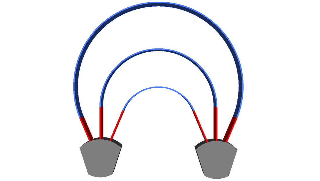
The diagram below is interactive. Move your mouse over different parts to view information about them.
Please Note
The solution bellow is interactive. To download the program necessary to run it click here. Simply move the sliders or type a number into the selection boxes to alter the solution . However you will not be able to see you selection inside the selection boxes. Make sure to press enter after you have typed a number. If you can, try to avoid using Internet Explorer to view this page because other web browsers like Firefox and Chrome tend to work better.
Having Problems? |
Information
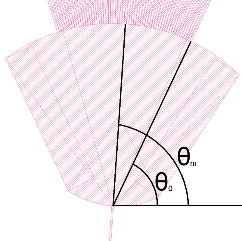
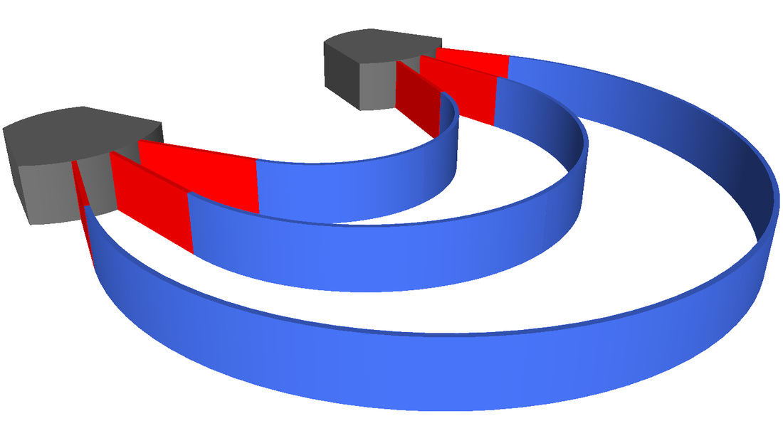
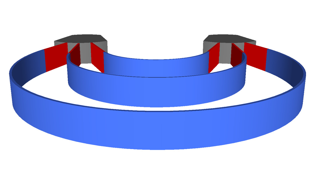
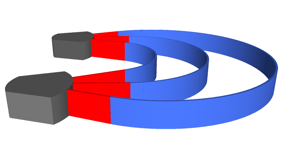
This is a solution of an Arrayed Waveguide Grating that has two sections that are vertical reflections of each other. Both of these sections are composed of two segments: a straight line segment with length sn and a curved segment which has a radius of rn. Where n is the number of the section starting at 0 (0 being the first)
The sliders allow you to modify the solution. The r0 and s0 sliders allow one to change the lengths of the starting sections. The θm slider changes the angle of the middle Waveguide with respect to the x-axis. The input boxes also allow you to modify the solution. The NOWG input changes the Number of waveguides. Additionally the Ra input changes the Rowland radius. The wa input changes the waveguide width at the free propagation region. Another input is labeled Δwa, this input box changes the space between waveguides. Finally the ΔL input changes the difference in length between two consecutive waveguides devided by two. This solution outputs the length of the line segments and the length of the radius as a function of the angle of that waveguide those segments are a part of. This information can be viewed most easily in its graph form. In the graph the blue dots represent the radii of the curved segments. The pink dots, on the other hand, represent the lengths of the S2 segments. However if you wish to see the exact lengths of each and every segment simply switch the Data selection to the appropriate tab. The S1 and S2 reveal the lengths of the S1 and S2 segments respectively. The WGS option reveals the exact numbers of the waveguide spacing.
|